Proper installation of armoured cables is essential to ensure electrical safety, long-term performance, and compliance with local standards. Even the highest-quality cable can fail prematurely if installed incorrectly—leading to costly repairs, equipment downtime, or safety hazards.
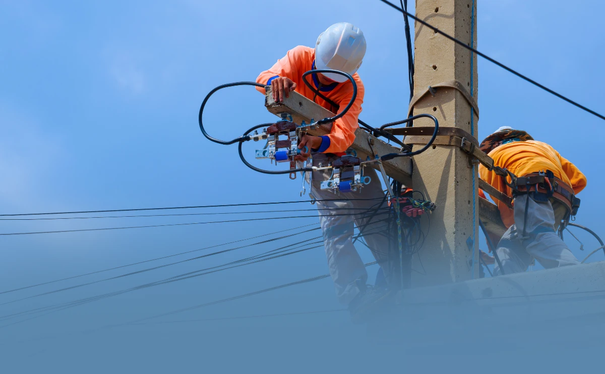
Armoured cables are specifically designed to provide extra mechanical protection against impact, moisture, and environmental stress. They are widely used in industrial, underground, and outdoor applications where durability and reliability are non-negotiable. However, to fully benefit from their robust design, every stage—from planning to final termination—must follow best practices and applicable standards such as IEC, NEC, or AS/NZS guidelines.
This article outlines key installation practices to help engineers, contractors, and project managers achieve safe, efficient, and long-lasting cable systems.
Table of Contents
Preparation: Site Inspection and Route Planning
Proper preparation is essential before the cable is laid. It helps prevent costly mistakes and ensures that the chosen cable type and installation method suit the project environment.
- Conduct a thorough site inspection
Before installation, inspect the site to identify environmental and physical conditions. Check for exposure to water, chemicals, mechanical stress, or temperature extremes. Understanding the terrain—whether underground, outdoor, or within industrial facilities—helps determine the right armoured cable type and necessary protection measures. Plan the cable route carefully
Define clear and direct routes to minimize unnecessary bends or mechanical strain. Avoid areas with sharp edges, high traffic, or potential interference from other services (such as water or communication lines). For underground installations, ensure the route allows sufficient burial depth and proper drainage to prevent long-term damage.Choose appropriate cable type and size
Select a cable rated for the application’s voltage, load, and environmental conditions. For example, steel wire armoured (SWA) cables are ideal for mechanical protection in industrial settings, while aluminium wire armoured (AWA) cables suit single-core systems to prevent magnetic interference. Oversizing slightly can improve safety and reduce voltage drop.Verify compliance with standards
Ensure all materials and components comply with national or international standards such as IEC 60502, AS/NZS 5000.1, or NEC Article 310. Compliance ensures consistent performance, fire safety, and electrical integrity throughout the system’s lifespan.Prepare proper tools and accessories
Gather approved glands, cleats, sealing compounds, and installation tools before starting. Using the correct accessories not only simplifies installation but also ensures proper grounding and moisture protection.
Installation Methods
Choosing the right installation method is crucial to ensure cable safety, longevity, and performance. The method depends on your site conditions, load requirements, and environmental exposure. Below is a quick guide comparing the most common installation approaches.
| Installation Method | Description | Best Used For | Key Considerations | Common Cable Type |
|---|---|---|---|---|
| Direct Burial | Cables are laid directly into the ground with protective coverings or sand bedding. | Long underground routes, outdoor power distribution, or remote installations. | Ensure correct burial depth and moisture protection. Avoid sharp stones and apply warning tapes. | SWA or STA armoured cables with moisture-resistant sheath. |
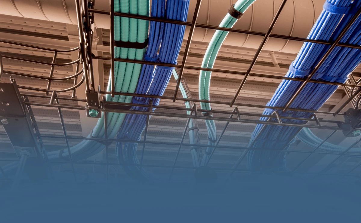
| In Conduit / Tray | Cables run through PVC, steel conduit, or cable trays for extra protection and accessibility. | Industrial plants, buildings, tunnels, and indoor systems. | Prevent overfilling conduits. Maintain bend radius and ensure adequate ventilation. | SWA or AWA armoured cables depending on core type. |
| Underground vs Overhead | Underground offers better protection; overhead is faster and cheaper to install. | Underground for reliability and safety; overhead for temporary or rural lines. | Underground systems require more planning and cost; overhead needs weather-resistant materials. | Underground: SWA or STA; Overhead: AWA or reinforced aluminum cables. |
Installation Steps of Armoured Cable
Proper installation ensures your armoured cables perform safely and efficiently over time. Follow these key steps to achieve a reliable and compliant installation.
Step 1: Site Survey & Hazard Mitigation
Underground utility mapping using electromagnetic locators (e.g., RD8000) to avoid excavation damage.
Environmental audit:
For corrosive sites, use halogen-free XLPE insulation (resists acids/alkalis).
For high-temp zones, use 90°C-rated XLPE cables (vs. standard 70°C PVC).
Zero-voltage verification: Multimeter test post-power cutoff to detect backfeed risks.
Step 2: Cutting & Length Optimization
Cutting formula: Actual length = Measured distance × 1.1 + Termination allowance (≥0.5m)4.
Tool requirement: Rotary cable cutters only (prevents armour deformation).
Bending radius compliance:
| Cable Type | Min. Bending Radius |
|---|---|
| SWA (Steel Wire Armour) | 12D |
| STA (Steel Tape Armour) | 20D |
Step 3: Critical Grounding Protocol
Armour grounding mandate:
Strip armour with 50mm bare segment for copper braid bonding.
Grounding resistance ≤4Ω (per IEC 60204-1 §8.2).
Conductor protection: Thermal sleeves repair insulation nicks (no tape fixes).
Step 4: Gland Selection & Sealing
IP-rated glands:
Outdoor: IP68 + dual Neoprene seals
Chemical zones: 316 stainless steel body.
Post-install test: Spray leak-detection foam to verify moisture resistance.
Step 5: Torque-Specified Termination
Terminal tightening standards (IEC 60364):
| Conductor Size | Torque Range (N·m) |
|---|---|
| 2.5 mm² | 0.8–1.2 |
| 16 mm² | 2.5–3.5 |
Corrosion prevention: Tin-plated lugs + NO-OX-ID grease for copper-aluminum interfaces.
Step 6: Mandatory Pre-Energization Tests
Insulation resistance: ≥100 MΩ/km (2500V megger, 1-min hold).
High-pot test: 15kV DC for 1 min (no flashover).
Continuity check: ≤0.1Ω resistance from armour to ground.
Technical Reference Table:
| Parameter | Standard Requirement | Failure Risk |
|---|---|---|
| Armour grounding | IEC 60204-1 §8.2 | Electric shock/lightning damage |
| Bending radius | 12–20× OD (per cable type) | Insulation cracking |
| Termination torque | IEC 60364 table A.2 | Overheating (>ΔT 40°C) |
| Insulation test | GB 50150-2016 Clause 6.0.2 | Post-energization short-circuit |
Common Installation Errors and How to Avoid Them
Even the best-quality armoured cables can fail if installed improperly. Here are three of the most frequent mistakes — and how to prevent them:
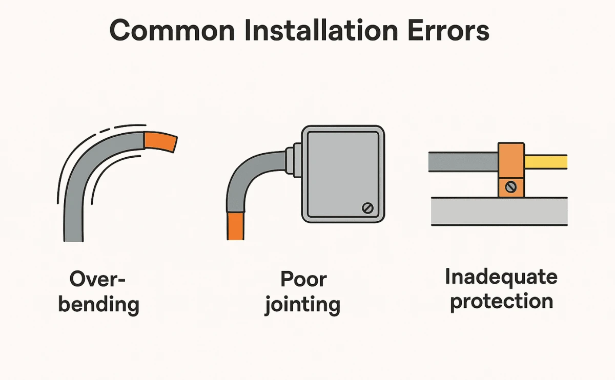
Over-bending
How it happens: Installers often bend the cable too tightly around corners, trays, or conduits to fit limited space, exceeding the manufacturer’s minimum bend radius.
Why it’s a problem: This stresses the insulation and armour layers, causing cracks or internal conductor damage that can lead to electrical faults.
How to avoid: Always follow the specified minimum bending radius (usually 12–15 times the cable’s overall diameter) and use gentle cable guides or rollers during installation.
Poor Jointing
How it happens: Using the wrong size or type of gland, failing to tighten terminations properly, or neglecting to connect the armour correctly for earthing.
Why it’s a problem: Loose or poorly fitted joints can cause overheating, arcing, and moisture ingress — all of which reduce cable lifespan and safety.
How to avoid: Choose the correct gland type (e.g., BW, CW, or A2), ensure tight mechanical fixing, and properly earth the armour according to installation standards.
Inadequate Protection
How it happens: Laying cables directly in soil without conduit, installing in areas prone to water accumulation, or insufficient mechanical shielding in high-traffic zones.
Why it’s a problem: Exposed cables are at risk of crushing, corrosion, or water damage, which can degrade insulation and lead to short circuits.
How to avoid: For underground installation, use protective conduits or ducts; for outdoor or mechanical risk areas, use steel tape or wire armoured cables with additional cover or warning tiles.
Maintenance Tips: Periodic Inspection & Insulation Resistance Tests
To keep armoured cables reliable and safe, regular maintenance is essential.
Periodic Inspection: Check for cracks, corrosion, or loose glands. Early detection prevents moisture ingress and mechanical damage. Inspect at least once a year or more often in harsh environments.
Insulation Resistance Test (IR Test): Use a megohmmeter to measure insulation health. Compare results with baseline readings—low values indicate ageing or moisture issues.
Check Connections: Ensure armour and gland terminations are tight and corrosion-free for proper grounding.
Keep Records: Log inspection dates and test results for future reference and safety audits.
Build with confidence. Choose NAN CABLE.
Correct installation is key to ensuring the safety, reliability, and long-term performance of armoured cables. With proper planning, disciplined installation practices, and routine inspection, you can significantly extend service life and avoid costly failures.
At NAN CABLE, we bring 40+ years of manufacturing experience and a strong track record in mega-projects worldwide. We supply high-quality armoured cables that meet IEC and AS/NZS standards and provide full technical support—from product selection to after-sales service.
Contact us If you need guidance for your project, our engineering team is ready to help you select the right armoured cable solution and ensure safe, reliable installation.
Visit our LinkedIn homepage for real-time technical consultation and project support directly with our engineers.